NASA Student Launch - Payload


Introduction
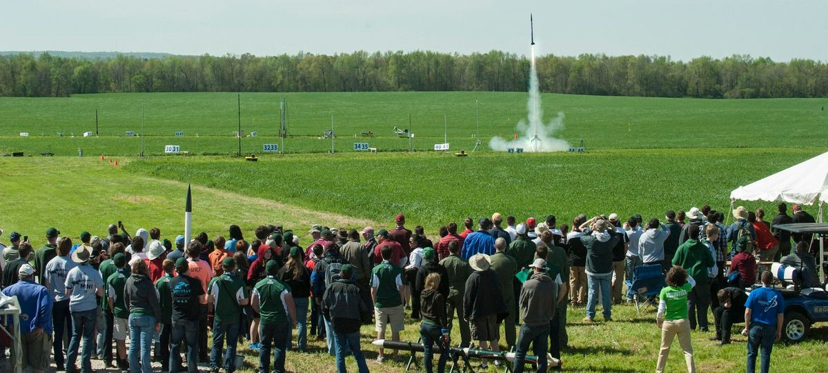
The NASA Student Launch is a nationwide project in which teams from different colleges will research, design, and construct a fully functional small-scale rocket with the intent to deliver a payload to a target altitude. This project also provides NASA with cost-effective and relevant research and information for the Space Launch System (SLS). The rocket will launch and deliver its payload 5,000 feet in the air. After the launch, the payload will receive a radio command to take a photo of surroundings, which will then be stored onboard and recovered along with the rocket. The scope of effort for this project specifically focuses on the payload portion of the rocket, though some analysis will be done on the vehicle. Success criteria for this project is meeting all minimum requirements, listed below.
Rocket Requirements
The requirements listed below must all be met in order to be considered a successful launch, so even though a rocket may launch off the ground without issue, it may fail based on requirements for what happens in the air and on the ground after descent.
1.) The payload must be delivered to a target altitude between 4,000 and 6,000 feet.
2.) The total impulse will not be greater than 5,120 Newtons.
3.) There must be a static stability of 2.0 at the rail exit.
4.) Rocket must have a thrust-to-weight ratio of 5:1.
5.) Post-deployment, the main chute will be deployed no lower than 500 feet.
6.) Maximum kinetic energy upon landing is 75 foot-pounds.
7.) The rocket must fully descend within 90 seconds.
8.) The rocket must descend within 2,500 feet of the launch area.
9.) Payload camera must swivel 360 degrees to take image of surrounding area.
10.) Payload camera must have a field of view of no less than 100 degrees.
11.) Camera must receive RF commands to perform given tasks.
Engineering Merit
The engineering merit specifically relevant to this project and many contained analyses includes an ability to understand and apply techniques from statics, mechanics of materials, and mechanical design. Examples of their application can be seen in the analysis section, specifically in those performed to find the critical buckling load of the payload lead screw and other important characteristics.
Results
Testing for the payload thus far has demonstrated component success through and through. The rotation stop will support the required weight, the camera mount will rotate to a sufficient angle and the camera will be extended into position very quickly. The success of these tests demonstrates the likeliness of a successful payload deployment during/after a rocket flight. Additionally, all of these are repeatable tests, and can be performed again if necessary.

Figure 1: Example of Student Launch

Table 1: Test Results
Analysis
The main focus of this project is the payload of the rocket, particularly on an alternative design for the deployment system. Specific analyses being done for the forces surrounding the payload, the deployment system, and the mechanism to hold the nosecone together. Analyses are performed using a variety of methods, including kinematics, statics, mechanics of materials, and principles of mechanical design.
One of the first important analyses performed involved finding forces on the payload, specifically the dry friction force that would be caused by the nosecone being in contact with the ground. Using a weight of 4 pounds for the nosecone and a coefficient of friction of 0.35, the friction force was found to be 1.4 pounds, which was then used directly in Analysis 8 (see Figure 2) to find the necessary power output for the motor needed to extend the payload and expose the camera.
Another interesting analysis performed was for a conceptual solution to holding the nosecone together during launch, making use of small cylindrical magnets. The requirement for the magnets is that they can oppose 240 Newtons of force (53.95 pounds). The chosen magnets were grade N52 neodymium magnets that are 4mm in diameter and 8mm in length. According to the manufacturer, the magnets individually have a pull force of 1..79 pounds, which means 30 are required to meet the requirement. Just to be safe, the amount is "rounded" up to 40. These magnets are also incredibly light, with a total weight of 0.067 pounds, meaning they'll have a negligible effect on the weight of the rocket.
Another set of analyses was performed, this time in a series of three, which was based on finding the properties of the lead screw used in this alternate design, with the ultimate goal of using either Johnson's or Euler's formula to find the critical buckling load. This is to ensure that the lead screw would never be a point of failure in the payload, which wasn't expected to happen but doesn't hurt to confirm regardless. The analyses involved finding the area moment of inertia, slenderness ratio, critical slenderness ratio, and radius of gyration. When the slenderness ratio was found to be greater than the critical slenderness ratio, Euler's formula was used, and the critical buckling load was determined to be 3,349.6 pounds, which is far more than the amount of force that the lead screw would need to support. The series can be seen below.
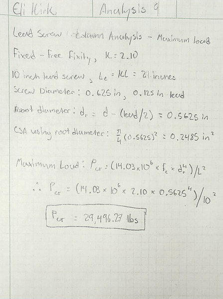
Figure 4: Lead Screw Maximum Load

Figure 5: Lead Screw Slenderness Ratio
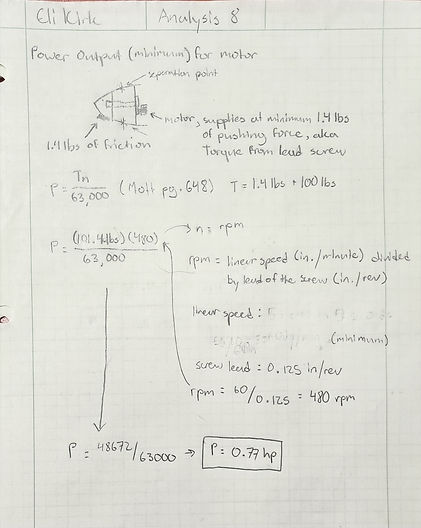
Figure 2: Power Output Analysis

Figure 3: Magnet Analysis
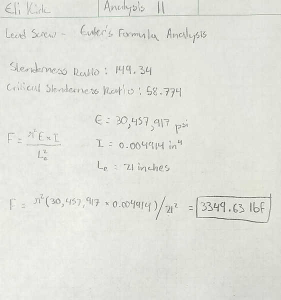
Figure 6: Lead Screw Critical Buckling
Construction
As of winter quarter, the approach to constructing the payload and manufacturing its components has changed a bit. Important to note, the alternative design shown in the analyses above has been dropped, the team is moving forward with the primary design. The major components of the payload (almost everything in the drawing tree) will be 3D printed with a nylon carbon fiber filament. This change has added time to the manufacturing stage of the process, though the parts will now be easier to make, as well as re-make if changes are made. The primary reason for this change was difficulty in using laser cutting to make the plate pieces out of a sheet of polycarbonate material. Additionally, the team had difficulty in coming up with efficient manufacturing methods for each part, and the variety was a bit more than what would be reasonable.
A few of the parts are made out of polycarbonate, specifically the nose and mid plates, the rotation stop for the camera mount, and the reinforcements for the plates. These parts were initially expected to be cut out using a laser cutter, but the material was only melted/burned by the laser instead of being cut. as shown in Figure 11. The parts were cut out by specialized tools from a team member, including a bandsaw to cut the rotation stop.
During the assembly portion of construction, the payload was inserted into the body tube - both have shown functionality thus far, these images preceded the test flight, which went very well and nothing was damaged. The initial plan was to epoxy everything together. Later, the payload was instead fastened to the body tube by drilling holes, then inserting screws from the outside to hold it in place.
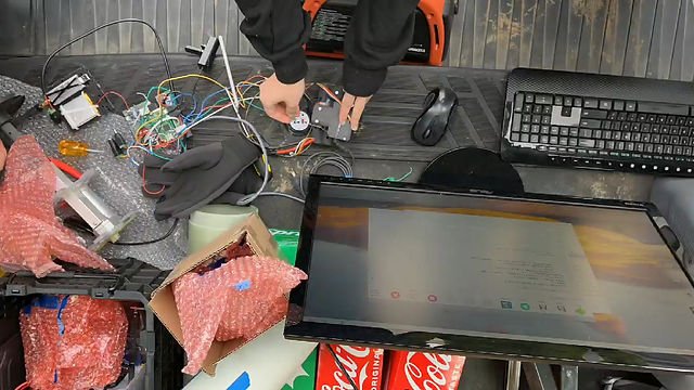
Figure 14: Electronics Timelapse
This is a quick timelapse of team members Kallysta Ray and Ethan Stapleton configuring the electronics board for the payload.
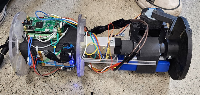
Figure 16: Assembled and Functional Payload

Figure 17: Drawing Tree
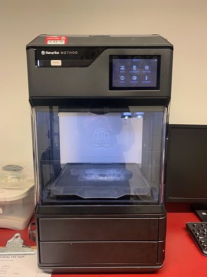
Figure 9: Part being 3D printed
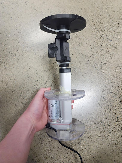
Figure 11: First Payload Construction
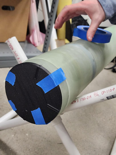
Figure 13: Payload Inserted Into Body Tube
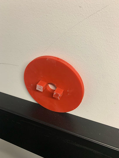
Figure 10: Base Plate
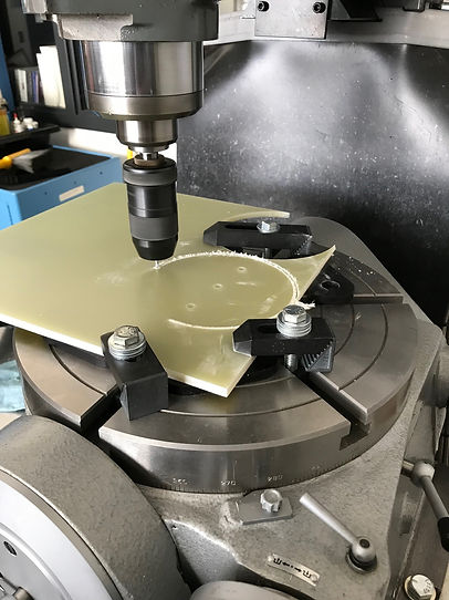
Figure 12: Fiberglass Bulkhead Being Cut
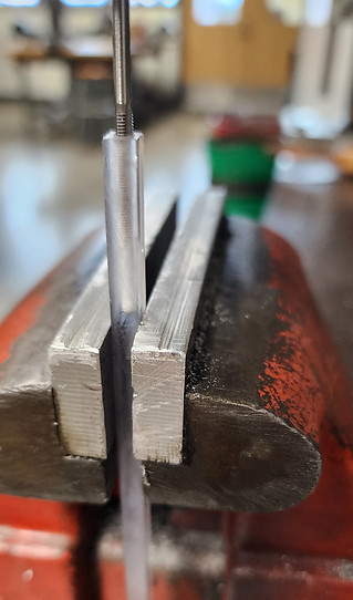
Figure 15: Rotation Stop Tapping
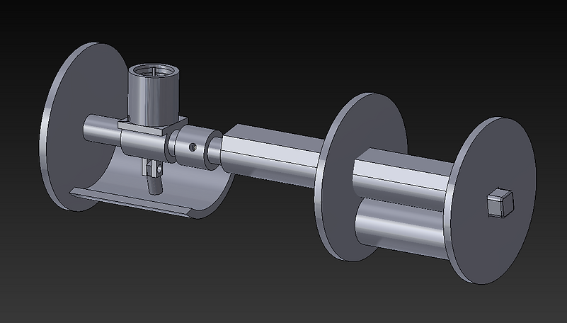
Figure 27: Preliminary Payload 3D Model
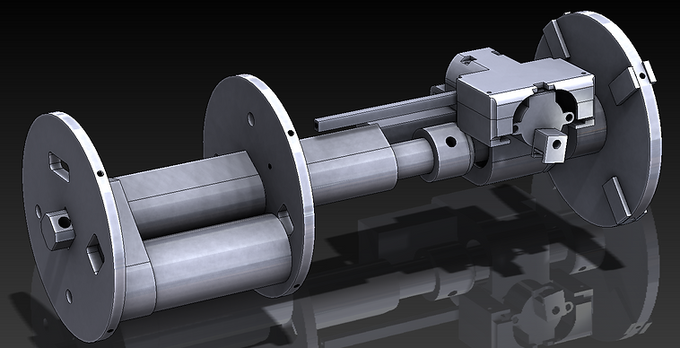
Figure 28: Final Payload 3D Model
Testing
Testing for this project is mostly small tests done on individual components for the payload. Each component serves a unique purpose and has a functional requirement, and testing will focus on primarily stress testing to determine whether a component will perform its task or will be strong enough to ensure a successful launch and deployment.
Rotation Stop Deflection: The rotation stop deflection test, shown in Figure 18, is intended to demonstrate the polycarbonate rotation stop's ability to withstand roughly 1 pound of force, the amount it will undergo during flight. This test was more than successful, as shown by Figure 18, where the rotation stop is being loaded with about 32 pounds of force.
Camera Mount Extension: For this test, the speed at which the camera mount reaches full extension is tested. The rotation stop holds down a spring, and once the stop is removed, the spring will extend quickly, forcing the mount into full extension. To test this, videos were taken for each trial, and the video timestamps are how the time for each extension trial is measured.
Camera Rotation Angle: This test is performed with the purpose of finding the angle to which the camera mount will rotate after the linear actuator extends. The test will demonstrate the effectiveness of the battery as a counterweight, in addition to the ability of the mount to rotate and move the camera to an upright position.
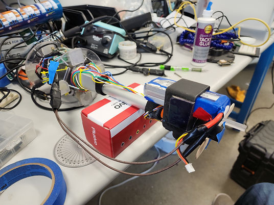
Figure 24: Angle Test Setup
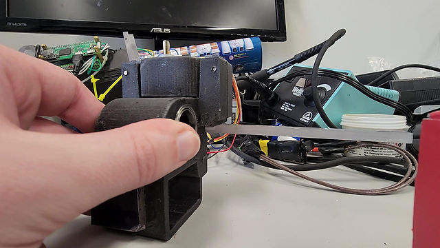
Figure 25: Extension Test

Figure 18: Rotation Stop Deflection Test

Figure 19: Rotation Stop Deflection
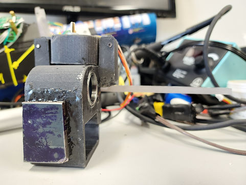
Figure 20: Camera Mount Extension Test

Figure 21: Camera Mount Extended
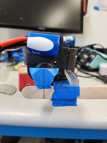
Figure 22: Angle Test
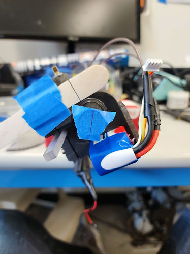
Figure 23: Post-Test Angle
Schedule
The schedule for this project is divided into three phases: design, construction, and testing. The design phase takes place in the fall quarter of the 2022 - 2023 school year, which involves analysis and documentation to find all important information surrounding the payload. Models of various parts are made in or imported to SolidWorks, which results in engineering drawings being created. The end of the design phase is marked by the submission of the CDR (Critical Design Review) to NASA by January 9th, 2023.
The construction portion of the project will take place during CWU’s Winter 2023 quarter. In this phase, the payload’s design will be finalized and ready to be tested. The design will be demonstrated to ensure it can keep up with the requirements, and any necessary changes will be implemented. In addition to the payload, the rest of the rocket will be constructed during this phase as well. This will include assembling the launch system and ensuring that all onboard electronics are functional and will perform on launch day.
Due to the high pressure schedule of the NASA Student Launch, the testing portion will also begin in the Winter 2023 quarter, specifically towards the end of February. This will include testing the ground ejection, how it behaves in the air, and testing how the payload performs under launch conditions. The Flight Readiness Report must be submitted by March 6th, 2023, which is the team's submission of the finalized project. Following this is the trip to Huntsville, Alabama where the NASA Student Launch takes place.
Important dates:
October 4th - proposal accepted
October 26th - PDR (Preliminary Design Review)
January 9th - CDR (Critical Design Review)
February 18th - First test flight
March 6th - FRR (Flight Readiness Review)
March 18th or April 1st - Second Test flight
April 15 - Huntsville launch
Budget
The budget for fall quarter is tame relative to the spending in winter quarter, as the vast majority of expenses for this project come after its finalization for travel costs. The spending for fall quarter is the components of the rocket. Many are already sourced, and will not add any cost. The estimated total spending for fall quarter is $2040.66, though some other minor costs may change that by a small amount.
The predicted final spending for the project is a little over $16,500. The project has a total fund of $17,000. This is a combined effort from the following sponsors of the project: Washington Space Grant, CWU Undergraduate Research Office, Club Funding, SLICE Funding, and solicited donations through foundation account. These funds are for use as the rocketry team sees fit, including purchasing materials, fabrication costs, and other expenditures related to travel.
Total spending for the finalized payload is around $375, which was more or less expected, if a little over. The rest of the budget just barely covered the cost of travel and construction of the rocket body, and funding has been fully utilized as of 4/21/2023.
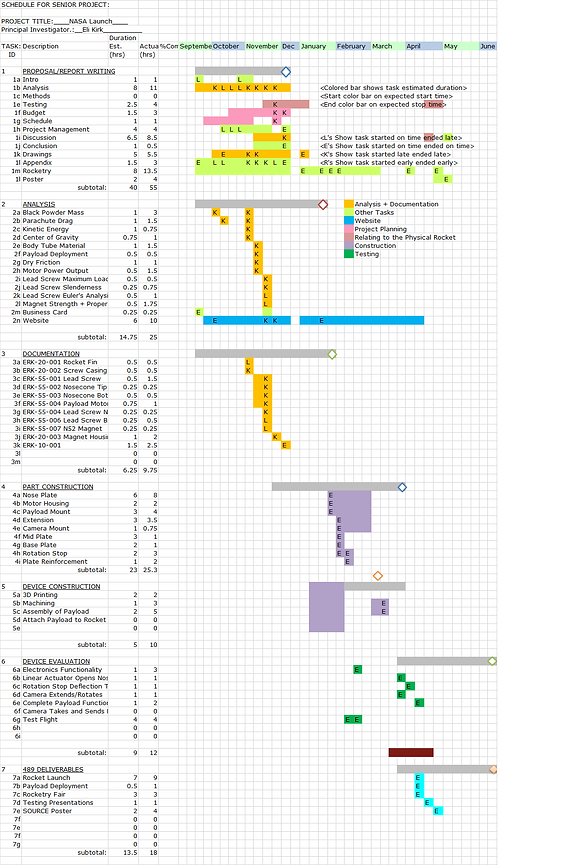
Figure 7: Gantt Chart (click to expand)
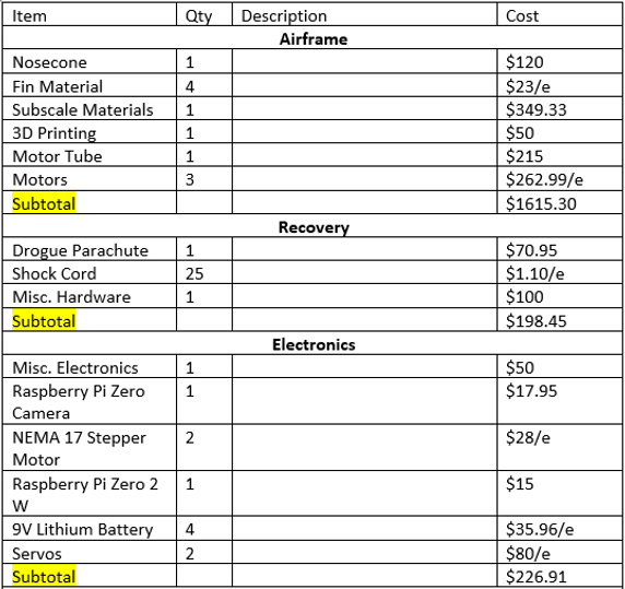
Figure 8: Budget/Expenditures
About the Engineer
Eli Kirk is a passionate mechanical designer with great ability to problem solve, learn, and adapt. Across this year-long project, he sharpened his project management skills, working both independently and with teammates to deliver a payload that remotely deploys and captures a photo of its surroundings.
This project was completed in collaboration with two other mechanical engineers, Ethan Stapleton and Kallysta Ray.
Ethan's Website: https://stapletone5.wixsite.com/cwu-nasa-student-roc
Kallysta's Website: https://raykal6.wixsite.com/seniorproject
